Top Industrial Automation and Electrical Instrument from HKXYTECH
  • GE IC693ACC302 Auxiliary Battery Module

GE IC693ACC302 Auxiliary Battery Module

2016-05-23 02:16:20

Description:

Auxiliary Battery Module IC693ACC302 GFK-2124A for Series 90 and PACSystems April 2005 The optional IC693ACC302 Auxiliary Battery Module provides an extended memory backup time compared to that of the standard memory backup batteries for Series 90-30, Series 90-70, and PACSystems CPUs. The Auxiliary Battery Module replaces the standard CPU RAM backup battery in your control system. Related Documents Series 90-70 Installation Manual, GFK-0262 Series 90-30 Installation Manual, GFK-0356 PACSystems RX7i Installation Manual, GFK-2223 PACSystems RX3i System Manual, GFK-2314 Date Code Pre-installation Check Carefully inspect all shipping containers for damage. If any equipment is damaged, notify the delivery service immediately. Save the damaged shipping container for inspection by the delivery service. After unpacking the equipment, record all serial numbers. Save the shipping containers and packing material in case it is necessary to transport or ship any part of the system. Date Code The date code is located on the product label on the front of the auxiliary battery module. The date code consists of three digits, such as 211. The first digit represents the year of manufacture in the 21st century; such as 2 for 2002. The last two digits represent the fiscal week of manufacture; for example 11 stands for fiscal week 11. Battery packs that have been in storage for several years (depending on the CPU type and how critical the application is) should be discarded because these units have a finite shelf life of seven years. Installation 1. With power removed from the equipment, drill four #29 (0.136 ) holes in the panel mounting surface, and tap for #8-32 threads, according to the hole pattern shown in the following figure. Use care to keep metal chips from falling into other equipment. 5.253\" (133.43 mm) 1.746\" (44.35 mm) #8-32 (four places) 2 Auxiliary Battery Module GFK-2124A 2. Securely attach the Auxiliary Battery Module to the panel mounting surface using four #8-32 x flat head machine screws. 3. Connect the cable from the battery module to the battery connector on the PLC. (Note that the battery will begin to drain immediately unless power is applied. To maximize battery life, it is recommended that you install it after power has been turned on.) 100 - 240 VAC PROGRAMMABLE CONTROLLER + PWR OK RUN BATT GE Fanuc Serie s 90 - 30 POWER SUPPLY 50/60 HZ 100VA 125VDC, 50W INPUT 24 VDC OUTPUT 0.8A MAX. HIGH CAPACITY B A T T E R Y Slot in bottom of power supply The battery connector is located on the power supply module in the CPU baseplate. The cable must be routed through the slot in the bottom of the battery compartment. Series 90-30 The battery connector is on the CPU module. The cable must be routed out the bottom of the CPU module. Series 90-70 Central Processor Unit OK ENABLE RUN Opening in bottom of CPU module Notch at base of battery compartment The battery connector is on the CPU module. Run the battery cable into the notch at the bottom of the battery compartment and close the battery door. PACSystems RX3i The battery connector is on the CPU module. Run the battery cable through the slot on the battery door and reinstall the battery door. An earlier version RX7i CPU may not have a notch in its battery door. For these CPUs, either replace the door (supplied with the IC698ACC701 replacement battery) or leave the door off. PACSystems RX7i BATTERY Slot in ACCESS battery access door Be careful not to pinch the battery cable when closing the battery compartment cover. Auxiliary Battery Module 3 GFK-2124A 4. Remove the standard memory backup battery from the system after installing the auxiliary battery module. Note: Refer to the appropriate installation manual for details on avoiding loss of PLC memory contents when replacing a memory backup battery. The standard memory backup battery must be removed from the system when using the auxiliary battery module. Diagnostics Note: Any testing of this unit should be performed only by qualified personnel who are trained in electrical safety practices and procedures. This unit is not user-serviceable. The unit has a built-in 1-Amp fuse that will open if the unit is subjected to a short-circuit or severe overload condition. This fuse is sealed inside the battery pack and is not replaceable. To test the unit if you suspect that the fuse has opened, turn off PLC power, unplug the battery unit, and carefully check the battery cable connector pins for presence of voltage with a volt meter. If voltage is present, the fuse is not open. If no voltage is present, the internal fuse has probably opened and the unit will have to be replaced. Disposal Once this product has lived its useful life, dispose of it safely according to the battery manufacturer s Material Safety Data Sheet (MSDS) that is included with this product. Specifications Parameter Specification Battery capacity 15.0 Amp-hours Physical dimensions 5.713 long x 2.559 wide x 1.571 high (145.1 x 65.0 x 39.9 mm) Case material Black, flame-retardant ABS plastic Connection 2.0 (0.6 meter) twisted red/black 24 AWG lead with female 2-pin connector Compatibility Compatible with battery connectors on Series 90-30 power supplies, Series 90-70 CPUs, and PACSystems CPUs Operating temperature range 0 to +60 C Shelf life 7 years Estimated memory backup life IC693CPU374 15 months Series 90-30 (IC693) CPUs 311 364 All Series 90-70 (IC697) CPUs 75 months……

MANUFACTURER: GE-IP DESCRIPTION: HIGH CAPACITY BATTERY PACK WEIGHT: 1 LBS :: ≈ 1 KGS WARRANTY: 1 YEARS PRODUCT REVISIONS AVAILABLE: OTHER AVAILABLE REVISIONS OF THE IC693ACC302 : A, B, C, D, E, F, G, H, I, J, K, L, M, N, O, P, Q, R, S, T, U, V, W, X, Y, Z

New Products

Siemens 6DL1193-6TP00-0DH1 SIMATIC ET 200SP HA

Siemens 6DL1193-6TP00-0DH1 SIMATIC ET 200SP HA, Terminal block, Type H1, 32 push-in terminals, internal reference temperature New load group, width: 22.5 mm.

Siemens 6DL1193-6TP00-0BH1 SIMATIC ET 200SP HA

Siemens 6DL1193-6TP00-0BH1 SIMATIC ET 200SP HA, Terminal block, Type H1, 32 push-in terminals, internal reference temperature Width: 22.5 mm.

Siemens 6DL1193-6GC00-0NN0 SIMATIC ET 200SP HA

Siemens 6DL1193-6GC00-0NN0 SIMATIC ET 200SP HA, carrier module 8-fold carrier for holding 8 I/O modules of the ET 200SP HA.

Siemens 6DL1193-6GA00-0NN0 SIMATIC ET 200SP HA

Siemens 6DL1193-6GA00-0NN0 SIMATIC ET 200SP HA, carrier module 2-fold carrier for holding 2 I/O modules of the ET 200SP HA.

Assortments

Description

Auxiliary Battery Module IC693ACC302 GFK-2124A for Series 90 and PACSystems April 2005 The optional IC693ACC302 Auxiliary Battery Module provides an extended memory backup time compared to that of the standard memory backup batteries for Series 90-30, Series 90-70, and PACSystems CPUs. The Auxiliary Battery Module replaces the standard CPU RAM backup battery in your control system. Related Documents Series 90-70 Installation Manual, GFK-0262 Series 90-30 Installation Manual, GFK-0356 PACSystems RX7i Installation Manual, GFK-2223 PACSystems RX3i System Manual, GFK-2314 Date Code Pre-installation Check Carefully inspect all shipping containers for damage. If any equipment is damaged, notify the delivery service immediately. Save the damaged shipping container for inspection by the delivery service. After unpacking the equipment, record all serial numbers. Save the shipping containers and packing material in case it is necessary to transport or ship any part of the system. Date Code The date code is located on the product label on the front of the auxiliary battery module. The date code consists of three digits, such as 211. The first digit represents the year of manufacture in the 21st century; such as 2 for 2002. The last two digits represent the fiscal week of manufacture; for example 11 stands for fiscal week 11. Battery packs that have been in storage for several years (depending on the CPU type and how critical the application is) should be discarded because these units have a finite shelf life of seven years. Installation 1. With power removed from the equipment, drill four #29 (0.136 ) holes in the panel mounting surface, and tap for #8-32 threads, according to the hole pattern shown in the following figure. Use care to keep metal chips from falling into other equipment. 5.253\" (133.43 mm) 1.746\" (44.35 mm) #8-32 (four places) 2 Auxiliary Battery Module GFK-2124A 2. Securely attach the Auxiliary Battery Module to the panel mounting surface using four #8-32 x flat head machine screws. 3. Connect the cable from the battery module to the battery connector on the PLC. (Note that the battery will begin to drain immediately unless power is applied. To maximize battery life, it is recommended that you install it after power has been turned on.) 100 - 240 VAC PROGRAMMABLE CONTROLLER + PWR OK RUN BATT GE Fanuc Serie s 90 - 30 POWER SUPPLY 50/60 HZ 100VA 125VDC, 50W INPUT 24 VDC OUTPUT 0.8A MAX. HIGH CAPACITY B A T T E R Y Slot in bottom of power supply The battery connector is located on the power supply module in the CPU baseplate. The cable must be routed through the slot in the bottom of the battery compartment. Series 90-30 The battery connector is on the CPU module. The cable must be routed out the bottom of the CPU module. Series 90-70 Central Processor Unit OK ENABLE RUN Opening in bottom of CPU module Notch at base of battery compartment The battery connector is on the CPU module. Run the battery cable into the notch at the bottom of the battery compartment and close the battery door. PACSystems RX3i The battery connector is on the CPU module. Run the battery cable through the slot on the battery door and reinstall the battery door. An earlier version RX7i CPU may not have a notch in its battery door. For these CPUs, either replace the door (supplied with the IC698ACC701 replacement battery) or leave the door off. PACSystems RX7i BATTERY Slot in ACCESS battery access door Be careful not to pinch the battery cable when closing the battery compartment cover. Auxiliary Battery Module 3 GFK-2124A 4. Remove the standard memory backup battery from the system after installing the auxiliary battery module. Note: Refer to the appropriate installation manual for details on avoiding loss of PLC memory contents when replacing a memory backup battery. The standard memory backup battery must be removed from the system when using the auxiliary battery module. Diagnostics Note: Any testing of this unit should be performed only by qualified personnel who are trained in electrical safety practices and procedures. This unit is not user-serviceable. The unit has a built-in 1-Amp fuse that will open if the unit is subjected to a short-circuit or severe overload condition. This fuse is sealed inside the battery pack and is not replaceable. To test the unit if you suspect that the fuse has opened, turn off PLC power, unplug the battery unit, and carefully check the battery cable connector pins for presence of voltage with a volt meter. If voltage is present, the fuse is not open. If no voltage is present, the internal fuse has probably opened and the unit will have to be replaced. Disposal Once this product has lived its useful life, dispose of it safely according to the battery manufacturer s Material Safety Data Sheet (MSDS) that is included with this product. Specifications Parameter Specification Battery capacity 15.0 Amp-hours Physical dimensions 5.713 long x 2.559 wide x 1.571 high (145.1 x 65.0 x 39.9 mm) Case material Black, flame-retardant ABS plastic Connection 2.0 (0.6 meter) twisted red/black 24 AWG lead with female 2-pin connector Compatibility Compatible with battery connectors on Series 90-30 power supplies, Series 90-70 CPUs, and PACSystems CPUs Operating temperature range 0 to +60 C Shelf life 7 years Estimated memory backup life IC693CPU374 15 months Series 90-30 (IC693) CPUs 311 364 All Series 90-70 (IC697) CPUs 75 months.
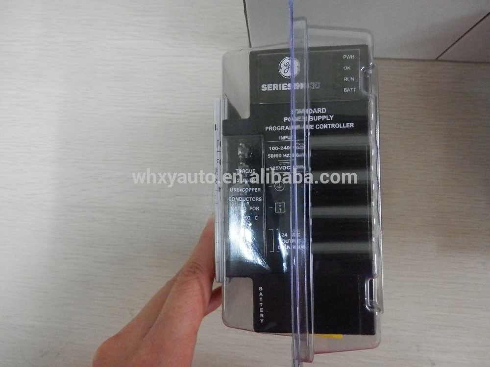
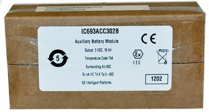
Photos